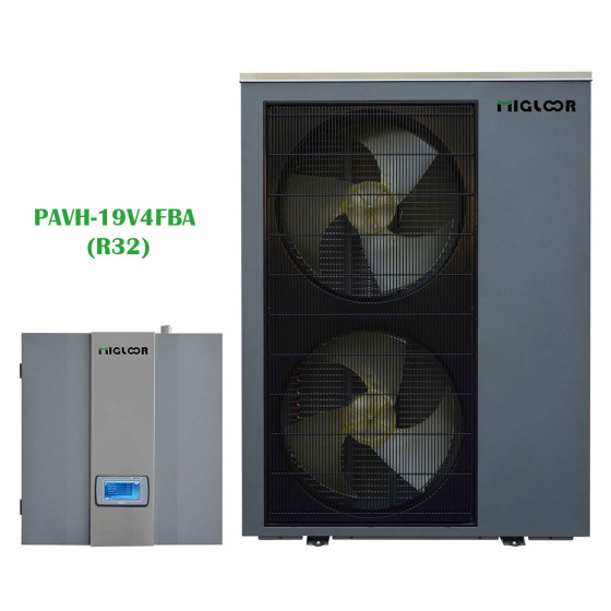


| MODÈLE | TYPE D'UNITÉ | PUISSANCE | DIMENSION |
|---|---|---|---|
| PAVH-19V4FBA | HeatStar Monoblock | 19kw | 1150*480*1610 |
Model |
|
heatSTAR+6M |
heatSTAR+9M |
heatSTAR+12M |
heatSTAR+15M |
heatSTAR+19M |
|
Power Supply / Refrigerant |
V/Hz/Ph |
220-240/50/1 - R32 |
380-420/50/3 - R32 |
||||
Max. Heating Capacity (1) |
kW |
6,5 |
9,2 |
11,6 |
15,35 |
18,5 |
|
C.O.P (1) |
W/W |
4,61 |
4,38 |
4,3 |
4,78 |
4,47 |
|
Heating Capacity Min./Max.(1) |
kW |
3.5 / 6.5 |
4.3/9.2 |
5.5 / 11.6 |
6/15.35 |
9.2/18.5 |
|
Heating Power Input Min./Max.(1) |
W |
758 / 1410 |
927/2097 |
1107 / 2683 |
1222/3209 |
1834/4142 |
|
C.O.P Min./Max.(1) |
W/W |
4.5 / 4.7 |
4.38/4.71 |
4.3 / 4.9 |
4.78/5.06 |
4.47/5.01 |
|
Max. Heating Capacity(2) |
kW |
6 |
8,6 |
11.2 |
14,26 |
18,2 |
|
C.O.P (2) |
W/W |
3,46 |
3,37 |
3.45 |
3,64 |
3,6 |
|
Heating Capacity Min./Max.(2) |
kW |
3.15 / 6 |
3.9/8.6 |
4.9 / 11.2 |
5.6/14.26 |
8.5/18.2 |
|
Heating power input Min./Max.(2) |
W |
943 / 1732 |
1162/2550 |
1401 / 3263 |
1551/3913 |
2248/4998 |
|
C.O.P Min./Max.(2) |
W/W |
3.34 / 3.56 |
3.37/3.58 |
3.3 / 3.5 |
3.64/3.82 |
3.6/3.82 |
|
Max. Cooling Capacity (3) |
kW |
7,45 |
9,5 |
9,8 |
18,57 |
22,5 |
|
E.E.R (3) |
W/W |
4,05 |
4,23 |
3,9 |
3,78 |
3,58 |
|
Cooling Capacity Min./Max.(3) |
kW |
6.22/7.45 |
6.7/9.5 |
7.2/9.8 |
7.23/18.57 |
8.5/22.5 |
|
Cooling Power Input Min./Max.(3) |
W |
1400/1863 |
1679/2242 |
1791/2510 |
1334/4917 |
1660/6285 |
|
E.E.R Min./Max.(3) |
W/W |
4.05/4.45 |
4.0/4.6 |
4.0/3.8 |
3.78/5.42 |
3.58/5.12 |
|
Max. Cooling Capacity (4) |
kW |
4,5 |
7,2 |
8,25 |
13 |
16 |
|
E.E.R (4) |
W/W |
2,7 |
2,8 |
2,9 |
2,96 |
2,85 |
|
Cooling Capacity Min./Max.(4) |
kW |
3.5/4.5 |
4.9/7.2 |
4.9 / 8.25 |
4.46/13 |
5.5/16 |
|
Cooling Power Input Min./Max.(4) |
W |
1330/1680 |
1451/2366 |
1358 / 2444 |
2592/4390 |
2970/5510 |
|
E.E.R Min./Max.(4) |
W/W |
2.5/2.74 |
2.8/3.1 |
2.6 / 3.5 |
2.96/3.29 |
2.85/3.2 |
|
Workable Ambient Temperature Range |
℃ |
-25~43 |
|||||
Min. System Water Temperature (Heating / Cooling) |
℃ |
20 / 7 |
|||||
Fuse of Circut Board (Indoor / Outdoor PCB) |
|
Indoor: 65TS/T15AL/250V |
Indoor: 65TS/T15AL/250V |
||||
Min. Floor Area for installation, operation and storage |
m2
|
0,8 |
1,9 |
3,1 |
6,2 |
8 |
|
Min. Area of Pipe-work |
m2
|
0,8 |
1,9 |
3,1 |
6,2 |
8 |
|
Max. Operation High Pressure |
MPa |
4.2 |
|||||
Max. Operation Low Pressure |
MPa |
1.2 |
|||||
Compressor |
Type - Quantity/System |
|
Twin Rotary - 1 |
Twin Rotary - 1 |
Twin Rotary - 1 |
Twin Rotary - 1 |
Twin Rotary - 1 |
Refrigerant |
Type / Amount |
- / kg |
R32 / 0.9kg |
R32 / 1.4kg |
R32 / 1.8kg |
R32 / 2.55kg |
R32 / 2.6kg |
Fan |
Quantity |
|
1 |
1 |
1 |
2 |
2 |
Airflow |
m3/h |
2500 |
3150 |
3150 |
6200 |
7000 |
|
Rated power |
W |
34 |
45 |
45 |
90 |
120 |
|
Noise Level (sound power) |
Indoor/Outdoor |
dB(A) |
44/52 |
44/53 |
44/52 |
44/59 |
44/61 |
Water Side Heat Exchanger |
Type |
|
Plate Heat Exchanger |
||||
Water Pressure Drop |
kPa |
26 |
26 |
26 |
26 |
26 |
|
Piping Connection |
Inch |
G1" |
G1" |
G1" |
G1-1/4" |
G1-1/4" |
|
Allowable Water Flow |
Min./Rated./Max. |
L/S |
0.21/0.29/0.35 |
0.26/0.43/0.52 |
0.34/0.57/0.68 |
0.43/0.71/0.85 |
0.55/0.92/1.1 |
Net Dimension(L×D×H) |
Indoor Unit |
mm |
570x550x255 |
570x550x255 |
570×550×255 |
570x550x255 |
570x550x255 |
Outdoor Unit |
mm |
1010x370x700 |
1165x370x845 |
1165x370x845 |
1085x390x1450 |
1085x390x1450 |
|
Net Weight |
Indoor Unit |
Kg |
25 |
25 |
25 |
25 |
25 |
Outdoor Unit |
Kg |
65 |
78 |
85 |
130 |
140 |
|
|
|
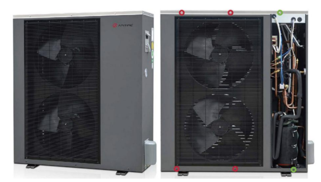
Les conceptions structurelles générales de nos produits ont été minutieusement développées pour faciliter au maximum l'installation et la maintenance. |
|
 |
 |
Structure de l'unité extérieure :4 vis pour ouvrir le protecteur du ventilateur afin d'accéder au système du ventilateur et au chauffage de la plaque inférieure. 2 vis pour ouvrir le panneau de service au système du compresseur. |
Structure de l'unité intérieure :Le panneau frontal s'ouvre comme une porte, offrant un accès aisé au système de contrôle. Toutes les connexions du contrôleur sont réalisées via des blocs de bornes, ce qui simplifie le câblage et le diagnostic des problèmes dans l'unité. En ouvrant le boîtier de contrôle comme une porte, le système hydraulique est entièrement exposé, ce qui offre suffisamment d'espace pour travailler sur n'importe quel composant à l'intérieur de l'unité. |
|
 |
 |
|
|
|
 |
 |
|
Notre application de contrôle de la pompe à chaleur via Wi-Fi permet aux utilisateurs de gérer les paramètres de base de la pompe à chaleur : activer et désactiver le système, modifier le réglage de la température, et changer le mode. |
|
rty
ewr